Spinning drives and fans are the 2 major sources of potential failures inside an otherwise reliable system. Replacing the traditional spinning drives will move the overall system-reliability up another notch. SSDs are not only more reliable, but generally faster in both ultimate read/write performance as well as access latencies which results to more responsive systems. There is plethora of choices of solid-state drives, and we’ll quickly look go through the interfaces and form factors that stuck around, and those that didn’t.
Definition
We will primarily look at SSDs. We’ll quickly discuss eMMC/DOM/CF/other simple flash based drives and cards here as they do not include an advanced drive controller, hampering performance and longevity of the on-board NAND flash. They are diminutive disks primarily designed for embedded use to hold OS images. The read performance varies from ok to slow, but the main concern is the slower write speeds and lowered write endurance. It is recommended for use in applications for highly read focused workloads.
Interface specification and what came before
We previously look at some of these connectors in more detail. Please hop on over if you have interest <link: https://www.aewin.com/application/internal-data-connectors/ >
We won’t go into detail here, but there are 3 more popular interfaces for attaching SSDs to host systems, and they are: SATA, SAS, and PCIe. SATA and SAS have long history of being used for storage. PCIe direct attached storage is a recent thing and has went through some trial and error until its current state. Although NVMe became synonymous with PCIe based SSDs, there were others that came before that never caught on. AHCI based PCIe drives were introduced before NVMe. AHCI was a logical interface designed for legacy spinning disks and could not take advantage of the extra speeds offered by SSDs. NVMe rescued us from the woefully inadequate AHCI standards by defining a standard from the ground up that aims to take advantage of extensible nature of PCIe as well as ever improving speeds of NAND flash-based drives and its controller. NVMe is a logical interface and can be carried in many form factors.
Form Factors
|
SSD
|
Interface |
PCIe Interface used |
| SATA |
SAS |
PCIe |
NVMe |
AHCI |
| Form Factor |
2.5″ |
V |
V |
V (U.2) |
V |
V |
| M.2 |
V (B or B+M Key) |
X |
V (M Key) |
V |
V |
| PCIe card |
X |
X |
V |
V |
V |
| mSATA |
V |
X |
X |
N/A |
N/A |
| EDSFF |
X |
X |
V (E1/ E3) |
V |
X |
| NF1 |
X |
X |
V (NGSFF/M.3) |
V |
X |
| SATAe |
X |
X |
V |
V |
V |
Note: Type of interface used for PCIe based SSD
Red = outdated format
mSATA
mSata is a miniaturized SATA drive, hence the name: micro-SATA. It is a popular format for embedded usage due to its smaller footprint. It has uses the PCIe mini connector and form-factor, but electrically uses the ubiquitous SATA interface, allowing it to be used in wide variety of platform.
M.2
M.2 is commonly what people think of solid-state drives today. It comes in many standard lengths, such as 22110, 2280, 2242, 2230, and 2224. It can be mounted parallel to the motherboard to allow lower height installation or mounted perpendicular to the motherboard in the case of the shorter drives. Parallel mounting does takes up valuable space on the PCB, whereas perpendicular has smaller footprint requirements. The trade-off is the lower density on the smaller drives usually used in this mounting. Longer drives may be perpendicularly mounted but is less secure and may require additional mechanical aids to affix it to the system.
One disadvantage of M.2 is thermal related. Majority of the M.2 is offered as bare PCB + chip without cooling solution on it. Without cooling, it is more likely to hit thermal limits in IOPS heavy workloads. It is potentially more fragile to physical forces or static discharge while handling without any barrier from touching bare PCB or components. On the other hand, this make it a compact solution that is 22mm wide that can easily squeeze into many places. Some systems may also use PCIe x2 lanes to the M.2, which limits the ultimate bandwidth to the M.2. If you require full bandwidth for the M.2, this is an area that should be specifically looked at.
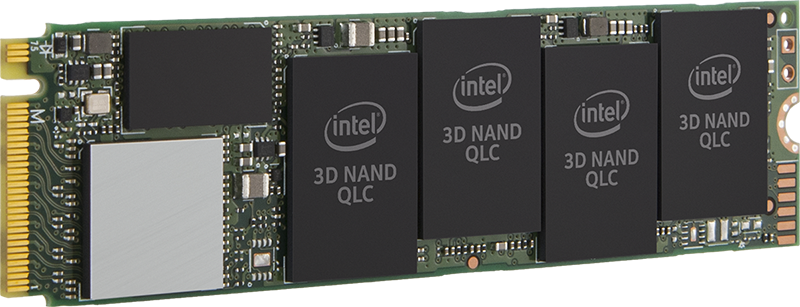 Picture originates from Intel
U.2
U.2 is a 2.5” drive form factor with PCIe x4 connection. It can be configured as 1x PCIe x4, or in special dual port drives, 2x PCIe x2 connections to increase redundancy in routing the data connection. It is available in 7mm, 9mm and 15mm thickness, with the higher performance drives typically in 15mm. This has long been the standard in datacenter focused SSD. The host receptacle is compatible with 2.5” SATA and SAS drives, and offer data and power through the same port.
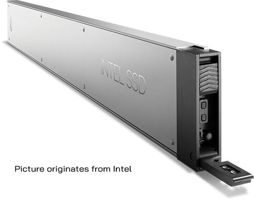
Intel Ruler
Intel Ruler is a slightly complicated topic, so we’ll just go over the overview today. Intel ruler is officially named EDSFF, Enterprise & Datacenter Storage Form Factor. It aims to replace the M.2 form-factor by aiming at the weakness of M.2. EDSFF has long variants that allows more NAND chips onboard for drastically increased capacity. On the other end, there are the E1.s short form factor that is small, but also install parallel to the motherboard, but with the slim edge toward the motherboard. This allows highest density and lower footprint on the host board. This also allows the form factor to be front mounted in a high-density configuration, limited by only the number of PCIe lanes available. It also took a page out of the Samsung NF1 playbook by increasing the width of the drives to increase NAND density.
- E1
- PCIe x4 connection
- Designed for 1U servers
- Short E1.s format
- Long E1.l format
|
|
- E3
- PCIe x16 connection
- Designed for 2U+ servers
- Short E3.s format
- Long E3.l format
|
 |
PCIe HHHL
PCIe add-on card form factor is likely the highest performing solid-state drives. It can offer PCIe x8 and x16 connection host, increasing the bandwidth. The class of controller used in these drives are typically higher performance as well to support the higher bandwidth. The form factor of the drive also allows larger heatsinks to keep the drive operating in top performance mode without degradation. The flipside of the coin to that performance is that it requires so many PCIe connections, limiting the number of drives that can be added. In a typical server class application, there are also limited number of slots, which are typically better used for other hardware, such as 100GbE NICs or accelerators. Only in very specialized cases that these make sense, such as large databases that require IOPS that couldn’t be achieved with another class of hardware.
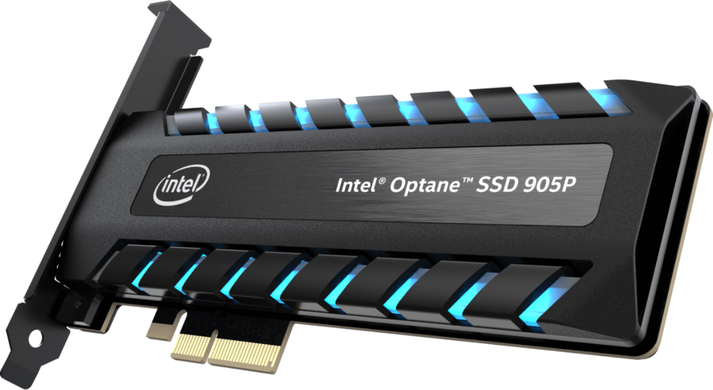
Picture originates from Intel
Honorable mentions:
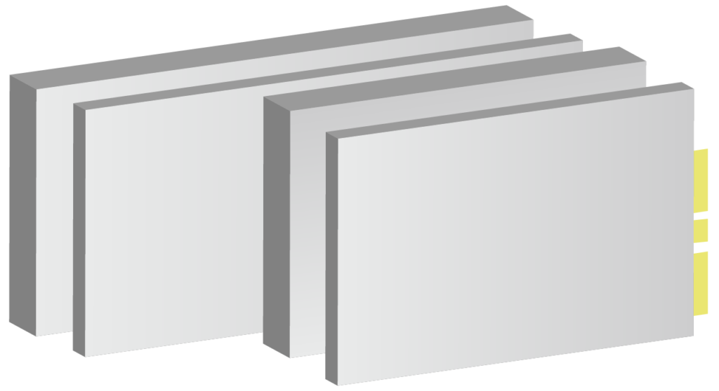
Samsung NGSFF/NF1 (“M.3”)
We would be remiss if we did not talk about the NF1. NF1 has some interesting feature of note, such as Dual Port capability NF1 for additional resilience for hardware faults, similar to dual port U.2. It examined the bottleneck of M.2 (the width) and expanded the width to allow higher density NAND modules to fit onboard. It also uses the same M-key M.2 connector, allowing hardware vendors to stock 1 less item… However, this is where the trouble starts. NF1 is electrically incompatible with M.2 while using the same connector. Worse yet, due to the pinout, it is possible to short some data pins to ground due to the different pin define. M.3 pin define is ill-thought through and fortunately Samsung has joined onboard with Intel’s EDSFF to avoid all the potential troubles this standard may cause.
SATAe
SATAe (SATA express), not to be confused with eSATA (external SATA), is a confusingly branded standard introduced in SATA 3.2 specification which used 2x side-by-side SATA connectors to carry PCIe signal. It was a form-factor that aimed to leverage the SATA connectors while allowing backwards compatibility on the host end to support 2x SATA drives. It was a big and cumbersome connector that industry is glad that never caught on.